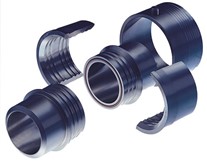
Dur O Lok® Couplings
Designed like a coupling. Performs like a flange.Made in the USA. Designed to ASME BPVC.


Save on maintenance, downtime, material costs, and space.
For decades, top refineries and industrial processors have trusted BETE DUR O LOK couplings to keep their piping systems running safely, efficiently, and dependably. Engineered to replace bulky ANSI flanges, DUR O LOKs are all-purpose, lightweight connectors delivering reliability across a wide range of operating temperatures. The compact, boltless design saves space, reduces installation time, eliminates the need for hardware, and minimizes alignment effort. It features a threadless, self-energizing seal and offers a wide range of material options for a thermally stable, corrosion-resistant, and low-maintenance solution.
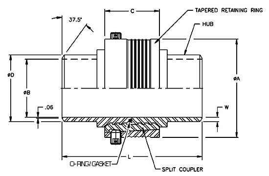
The heart of the DUR O LOK design is a system of wedge-shaped, circumferential teeth on the outside diameter of the hubs and the inside diameter of the mating split coupler. When assembled, the teeth generate a wedging action that compresses the gasket and brings the hub ends together. The split coupler’s tapered outside diameter accepts a matching tapered retaining ring that slides over the split coupler ring segments, forcing them together and holding them securely in place with a set screw. The entire connection process can be completed in under a minute, without wrenches.
By significantly reducing installation time, space requirements, and overall system weight without sacrificing strength, DUR O LOK couplings offer numerous advantages over traditional flanges. These benefits make them the preferred solution for many pipe-connecting applications, particularly in petrochemical processing and refining.

How It Works
Benefits
Reduce maintenance
Reduce materials cost
Reduce space requirements for pipe racks
Features
The DUR O LOK coupling meets the requirements of the following codes:
Compact - length and outside diameter reduced by 30% - 50%, compared to flanges. Allows double the number of pipes per rack and improves external flow distribution for immersed couplings. It will reduce shadowing for couplings used in process vessels.
Lightweight - weight reduced by 60% - 90%, compared to flanges.
Simple - Number of parts reduced by 55% - 75% per connection, compared to flanges.
Fast - Save up to 10-15 minutes to make or break each connection.
Non-restrictive - Full port inside diameter eliminates pressure drop and allows "pigging".
Smooth interior bore - Minimizes flow disturbances. It eliminates attrition in catalyst and other solids conveying applications.
Boltless and threadless - Only safety set screws required. No torque measurements are required. No bolt holes to align. No need to tighten connections after thermal cycling. Simplifies painting and insulating.
Thermally stable - Design minimizes thermal expansion effects on sealing. It will tolerate very rapid changes in external or internal temperatures.
No interference fits or metal-to-metal sealing - Higher reliability. Less susceptible to damage.


| DUR O LOK | Weld Neck Flanges | |||||||
|---|---|---|---|---|---|---|---|---|
| Pipe Size | Pipe Schedule | Overall Diameter (in) | Overall Length (in) | Approx Weight (lb) | Flange Class | Flange OD (in) | Flange Assembly Length (in) | Flange Assembly Weight (lb) |
| 1.00 | 80 | 2.50 | 3.50 | 1.99 | 2500 | 6.25 | 7.00 | 26.60 |
| 1.25 | 80 | 2.85 | 3.50 | 2.61 | 600 | 5.25 | 5.20 | 13.10 |
| 1.50 | XXS | 3.13 | 4.00 | 4.82 | 2500 | 8.00 | 8.80 | 57.00 |
| 2.00 | 80 | 3.55 | 5.00 | 5.25 | 2500 | 9.25 | 10.00 | 83.30 |
| 2.50 | 160 | 4.21 | 6.00 | 9.19 | 600 | 7.50 | 6.20 | 38.00 |
| 3.00 | 80 | 4.95 | 6.50 | 11.20 | 1500 | 10.50 | 9.20 | 102.50 |
| 3.50 | 80 | 5.45 | 7.00 | 13.64 | 600 | 9.00 | 6.80 | 63.20 |
| 4.00 | 160 | 5.95 | 7.50 | 20.54 | 2500 | 14.00 | 15.00 | 301.20 |
| 6.00 | 80 | 8.47 | 9.50 | 41.51 | 600 | 14.00 | 9.20 | 173.50 |
| 8.00 | 80 | 10.65 | 9.50 | 60.84 | 600 | 16.50 | 10.50 | 259.10 |
Please note that weight and dimensions information are approximate.
Please call if you have questions.
DUR O LOK® Pipe Couplings – Dimensions (in), Ratings (psi), and Assumed Moments (ft-lb)
Data provided below is for the o-ring design. Similar information is available upon request for the high temperature gasket seal design.
| Pipe Size | Pipe Sched. | "D" Pipe O.D. |
"B" Pipe I.D. |
"A" Overall Diameter |
"C" Tapered Ring Length |
"L" Overall Length |
"W" Nominal Wall |
Approx. Weight (lbs.) |
Pressure Rating (PSI)† Carbon Steel |
Pressure Rating (PSI)† 304 Stain. Steel |
Assumed Moment (ft-lb) |
|---|---|---|---|---|---|---|---|---|---|---|---|
| 1 | 40 | 1.32 | 1.05 | 2.50 | 1.47 | 3.50 | 0.14 | 1.99 | 1475 | 1229 | 33 |
| 1 | 80 | 1.32 | 0.96 | 2.50 | 1.47 | 3.50 | 0.18 | 2.10 | 2850 | 2374 | 33 |
| 1¼ | 40 | 1.66 | 1.38 | 2.85 | 1.47 | 3.50 | 0.14 | 2.41 | 1550 | 1291 | 59 |
| 1¼ | 80 | 1.66 | 1.28 | 2.85 | 1.47 | 3.50 | 0.19 | 2.61 | 2800 | 2332 | 59 |
| 1¼ | 160 | 1.66 | 1.16 | 2.85 | 1.47 | 3.50 | 0.25 | 2.81 | 4650 | 3873 | 59 |
| 1½ | 40 | 1.90 | 1.61 | 3.13 | 2.00 | 4.00 | 0.15 | 3.71 | 2250 | 1874 | 82 |
| 1½ | 80 | 1.90 | 1.50 | 3.13 | 2.00 | 4.00 | 0.20 | 4.00 | 3850 | 3207 | 82 |
| 1½ | 160 | 1.90 | 1.34 | 3.13 | 2.00 | 4.00 | 0.28 | 4.38 | 5900 | 4915 | 82 |
| 1½ | XXS | 1.90 | 1.10 | 3.13 | 2.00 | 4.00 | 0.40 | 4.82 | 8100 | 6747 | 82 |
| 2 | 40 | 2.38 | 2.07 | 3.55 | 2.00 | 5.00 | 0.16 | 4.70 | 1850 | 1541 | 140 |
| 2 | 80 | 2.38 | 1.94 | 3.55 | 2.00 | 5.00 | 0.22 | 5.25 | 3350 | 2791 | 140 |
| 2 | 160 | 2.38 | 1.69 | 3.55 | 2.00 | 5.00 | 0.35 | 6.19 | 5600 | 4665 | 140 |
| 2½ | 40 | 2.88 | 2.47 | 4.21 | 2.00 | 6.00 | 0.21 | 7.16 | 2100 | 1749 | 266 |
| 2½ | 80 | 2.88 | 2.32 | 4.21 | 2.00 | 6.00 | 0.28 | 8.10 | 3500 | 2916 | 266 |
| 2½ | 160 | 2.88 | 2.13 | 4.21 | 2.00 | 6.00 | 0.38 | 9.19 | 4700 | 3915 | 266 |
| 3 | 40 | 3.50 | 3.07 | 4.95 | 2.00 | 6.50 | 0.22 | 9.81 | 1600 | 1333 | 431 |
| 3 | 80 | 3.50 | 2.90 | 4.95 | 2.00 | 6.50 | 0.30 | 11.20 | 2900 | 2416 | 431 |
| 3 | 160 | 3.50 | 2.62 | 4.95 | 2.00 | 6.50 | 0.44 | 13.23 | 3900 | 3249 | 431 |
| 3½ | 40 | 4.00 | 3.55 | 5.45 | 2.00 | 7.00 | 0.23 | 11.75 | 1650 | 1374 | 599 |
| 3½ | 80 | 4.00 | 3.36 | 5.45 | 2.00 | 7.00 | 0.32 | 13.64 | 2850 | 2374 | 599 |
| 4 | 40 | 4.50 | 4.03 | 5.95 | 2.00 | 7.50 | 0.24 | 13.70 | 1550 | 1291 | 804 |
| 4 | 80 | 4.50 | 3.83 | 5.95 | 2.00 | 7.50 | 0.34 | 16.21 | 2400 | 1999 | 804 |
| 4 | 120 | 4.50 | 3.62 | 5.95 | 2.00 | 7.50 | 0.44 | 18.55 | 2700 | 2249 | 804 |
| 4 | 160 | 4.50 | 3.44 | 5.95 | 2.00 | 7.50 | 0.53 | 20.54 | 2700 | 2249 | 804 |
| 5 | 40 | 5.56 | 5.05 | 7.35 | 3.10 | 8.50 | 0.26 | 26.27 | 1750 | 1458 | 1363 |
| 5 | 80 | 5.56 | 4.81 | 7.35 | 3.10 | 8.50 | 0.37 | 30.45 | 2450 | 2041 | 1363 |
| 6 | 40 | 6.63 | 6.07 | 8.47 | 3.10 | 9.50 | 0.28 | 34.25 | 1600 | 1333 | 2124 |
| 6 | 80 | 6.63 | 5.76 | 8.47 | 3.10 | 9.50 | 0.43 | 41.51 | 2350 | 1958 | 2124 |
| 8 | 40 | 8.63 | 7.98 | 10.65 | 3.10 | 9.50 | 0.32 | 49.72 | 1350 | 1125 | 4202 |
| 8 | 80 | 8.63 | 7.63 | 10.65 | 3.10 | 9.50 | 0.50 | 60.84 | 1825 | 1520 | 4202 |
*DUR O LOK® Pipe Couplings - Note: Values for dimensions and weights are nominal; please contact Customer Service for exact values. Maximum Temperature: 400°F (204°C) with Viton o-ring, 450°F (232°C) with silicone rubber o-ring. Please note: Grafoil® limit in air or oxygen 850°F (454°C).
Warning: Low-temperature (OR70) and high-temperature (GRF100) design DUR O LOK couplings and their gaskets are not interchangeable.
BETE offers an assembly clamp (purchased separately) for fast and easy installation, ensuring proper alignment of the coupling hubs. If this clamp is to be used, refer to the attached DOL Clamp Instructions for more details.
Warning: Do not have a gasket or O-ring in place while welding, as damage will occur.
Warning: Protect the machined surfaces of the coupling from weld splatter.
Warning: Damaged gaskets must not be used, as they will not seal properly. Always replace used gaskets to ensure a proper seal. High-temperature (GRF100) gaskets are for one-time use only.

Warning: The tapered retaining ring must be fully engaged to attain the design compression and pressure rating for the desired service. The tips of the set screws must fit completely inside the split coupler’s set screw grooves. The coupling could become inadvertently disassembled due to vibration during use if not assembled properly. This may result in process material leakage.
BETE offers an assembly clamp for fast and easy installation, ensuring proper
alignment of the coupling hubs.

| Cookie | Duration | Description |
|---|---|---|
| cookielawinfo-checkbox-analytics | 11 months | This cookie is set by GDPR Cookie Consent plugin. The cookie is used to store the user consent for the cookies in the category "Analytics". |
| cookielawinfo-checkbox-functional | 11 months | The cookie is set by GDPR cookie consent to record the user consent for the cookies in the category "Functional". |
| cookielawinfo-checkbox-necessary | 11 months | This cookie is set by GDPR Cookie Consent plugin. The cookies is used to store the user consent for the cookies in the category "Necessary". |
| cookielawinfo-checkbox-others | 11 months | This cookie is set by GDPR Cookie Consent plugin. The cookie is used to store the user consent for the cookies in the category "Other. |
| cookielawinfo-checkbox-performance | 11 months | This cookie is set by GDPR Cookie Consent plugin. The cookie is used to store the user consent for the cookies in the category "Performance". |
| viewed_cookie_policy | 11 months | The cookie is set by the GDPR Cookie Consent plugin and is used to store whether or not user has consented to the use of cookies. It does not store any personal data. |