
LOW FLOW, MISTING, AND AIR ATOMIZING NOZZLES
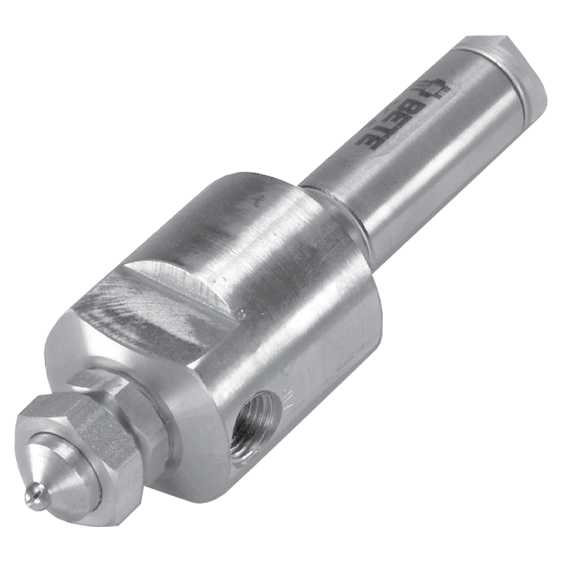
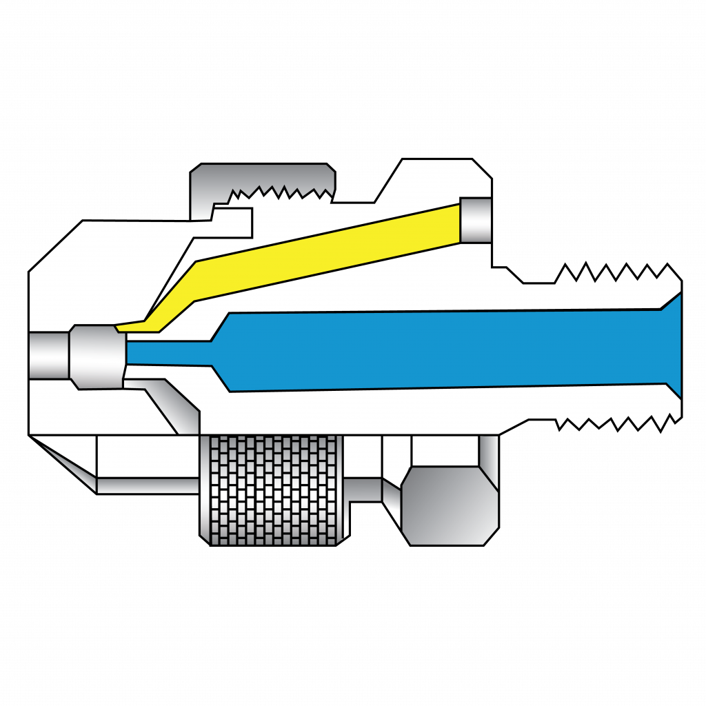
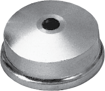
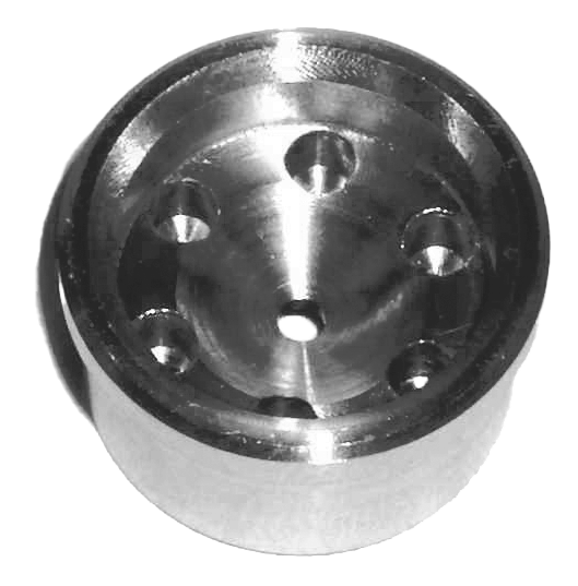
XA00 Body with End Plug
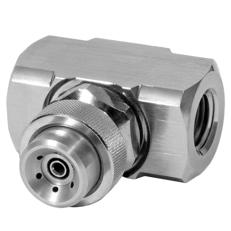
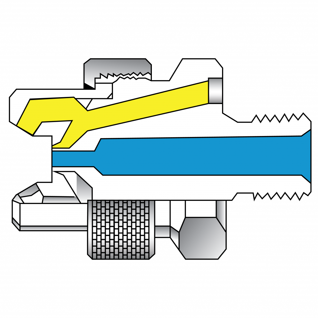
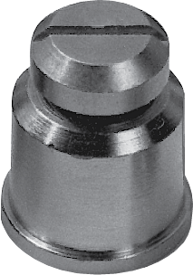
XA00 Body with Clean-out Hardware
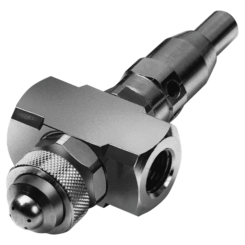
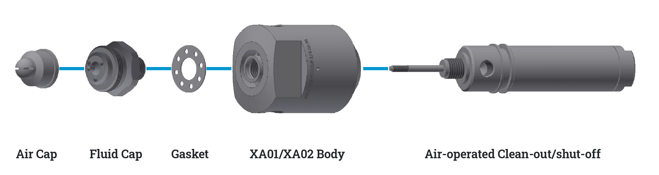
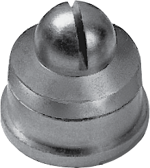
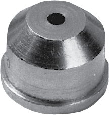
XA02 Body with Air-operated/Shut-off
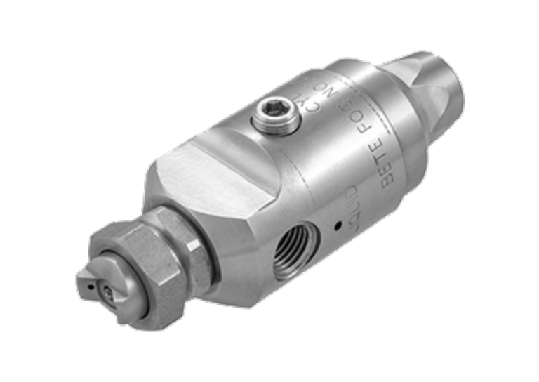
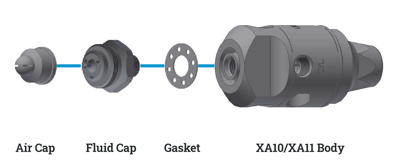
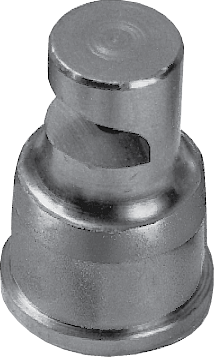
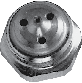
XA10 Body
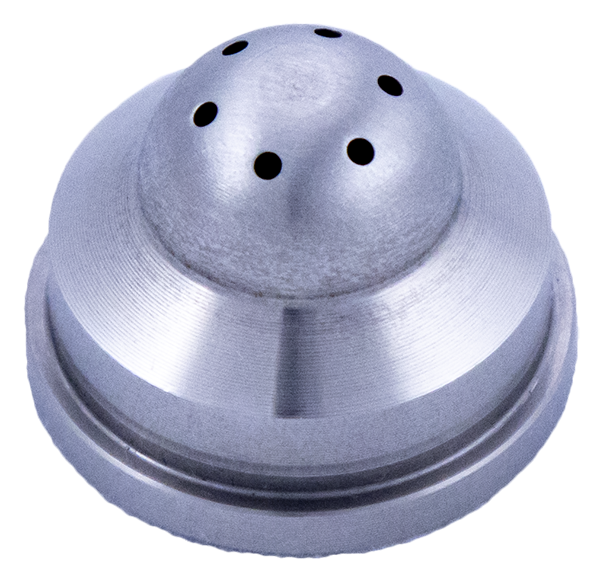
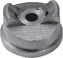
XA nozzles produce eight distinctly different types of sprays, depending on which interchangeable air and fluid caps are selected. The set-up determines the spray type and flow rate with a specific combination of one air cap and one fluid cap.
Types of Spray Set-Ups
Internal & External Mix Setups
Internal Mixing
- Liquid and air streams come together inside the nozzle and are mixed, and they exit through the same orifice.
- The streams are not independent; airflow changes will affect the liquid flow.
- Not suitable for viscous liquids above 200 cP.
External Mixing
- The air and liquid streams exit the nozzle independently through each orifice.
- Air and liquid flow rates can be independently controlled, allowing precise fluid metering.
- Suitable for all liquids, including viscous liquids above 200 cP.
Siphon Set-Ups
Internal and External Mix Set-ups require the liquid supplied to the nozzle under pressure from a municipal water supply, pump, or pressure vessel. Siphon Set-ups use the flow of compressed air within the nozzle to siphon liquid from a container. Siphon set-ups are frequently used for spraying additives from a container without a pump. They provide the lowest flow rates available in the XA series (as low as 0.1 GPH).
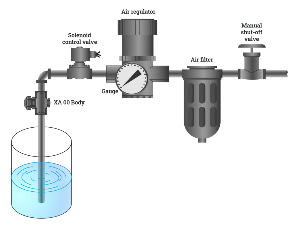
Pressure System Set-Ups
In a pressure-fed system, the liquid is supplied under pressure to either internal or external mix BETE XA Series nozzles. Air and liquid regulators control the fluid delivery pressure, while the air filter and liquid strainer ensure that the supplied fluids are of high quality. Operational control is maintained by manual or solenoid valves used in conjunction with the various hardware assemblies.

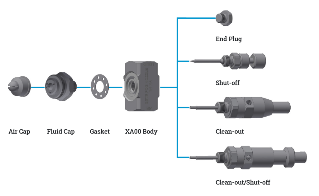
Basic XA Operation & Components
The basic XA spray nozzle assembly consists of a body, a spray set-up, and a hardware assembly that can provide shut-off and clean-out capabilities.
Non-Automatic
NON-AUTOMATIC
The basic XA body requires hardware assembly for manual shut-off or clean-out/shut-off.
Recommended Body Styles: XA00, XA03, XA05
Recommended Hardware Assemblies: End Plug, Shut-off, Clean-Out, or Clean-out/Shut-off
Automatic
AUTOMATIC
The round XA body can be equipped with an air cylinder to provide shut-off or clean-out/shut-off for automatic operation.
Recommended Body Styles: XA00, XA01, XA02, XA10, XA11
Recommended Hardware Assemblies: Air-operated Shut-off, or Air-operated Clean-Out/Shut-off
Spray Nozzle Assembly & Set-Up Numbers
Spray Assembly Part Numbers
Standard XA assemblies include an air cap, fluid cap, and body style and hardware assemblies and mounting hardware is optional. The chart below can be used as a guide for creating an XA spray assembly set-up number. For Set-Up Numbers please refer to the section “Air Cap & Fluid Cap Spray Set-Up Numbers.
*For extensions, end plug hardware is standard; air-operated hardware may be provided on an application-specific basis.
1/4
NPT
XA01
PR
250
E
01
12
Connection Size
Connection Type
Body Styles
Air Cap
Set-Up Number
Hardware Assemblies
Mounting Hardware
Extension Size*
1/8", 1/4",
and 1/2"
and 1/2"
NPT, BSP, B
00
PR
See specific code in chart below
A
01
12
01
FF
B
02
02
AD
C
03
03
XW
D
05
PF
E
06
EF
F
07
SR
08
SF
10
ER
11
12
Air Cap & Fluid Cap Spray Set-Up Number
Each of the seven air caps produces a unique spray pattern and flow rate when paired with a fluid cap. The set-up number is determined by the air cap (AC) and fluid cap (FC) combo. Please refer to the chart below.
AD Air Cap
EF Air Cap
SR Air Cap
XW Air Cap
PF Air Cap
FF Air Cap
ER Air Cap
PR Air Cap
Fluid Cap
Air Cap Series
Spray Pattern
Pipe Size BSP or NPT
Set-Up No.
Fluid Cap
Air Cap
AD
WIDE ANGLE ROUND
1/8 or 1/4
AD 050
FC 4
AC 1601
AD 100
FC 2
AC 1603
AD 150
FC 2
AC 1602
AD 200
FC 1
AC 1603
AD 250
FC 1
AC 1604
AD 300
FC 5
AC 1605
1/2
AD 5050
FC 501
AC 5601
AD 5100
FC 501
AC 5602
AD 5150
FC 501
AC 5603
AD 5200
FC 502
AC 5604
EF
FLAT FAN (EXTERNAL MIX)
1/8 or 1/4
EF 050
FC 7
AC 1001
EF 100
FC 7
AC 1003
EF 150
FC 4
AC 1001
EF 200
FC 4
AC 1003
EF 250
FC 3
AC 1001
EF 300
FC 3
AC 1003
EF 350
FC 6
AC 1002
EF 400
FC 6
AC 1004
EF 450
FC 2
AC 1002
EF 500
FC 2
AC 1004
EF 550
FC 1
AC 1002
EF 600
FC 1
AC 1004
EF 650
FC 8
AC 1005
EF 700
FC 9
AC 1005
EF 750
FC 5
AC 1005
1/2
EF 5050
FC 501
AC 5001
ER
WIDE ANGLE ROUND
1/8 or 1/4
ER 050
FC 7
AC 1801
ER 150
FC 4
ER 250
FC 3
ER 350
FC 6
AC 1802
ER 450
FC 2
ER 550
FC 1
ER 650
FC 8
AC 1803
ER 750
FC 9
ER 850
FC 5
FF
DEFLECTED FLAT FAN
1/8 or 1/4
FF 050
FC 10
AC 1701
PF
PRESSURE FLAT FAN
1/8 or 1/4
PF 050
FC 4
AC 1301
PF 100
FC 3
AC 1303
PF 150
FC 3
AC 1301
PF 200
FC 3
AC 1302
PF 250
FC 2
AC 1304
PF 300
FC 1
AC 1304
PF 350
FC 1
AC 1305
PF 400
FC 5
AC 1306
1/2
PF5050
FC 501
AC 5301
PF5100
FC 502
AC 5302
PR
PRESSURE ROUND
1/8 or 1/4
PR 050
FC 4
AC 1501
PR 100
FC 4
AC 1502
PR 150
FC 3
AC 1502
PR 200
FC 2
AC 1503
PR 250
FC 1
AC 1503
PR 300
FC 5
AC 1504
1/2
PR 5050
FC 501
AC 5501
PR 5100
FC 502
AC 5502
SF
SIPHON FLAT FAN
1/8 or 1/4
SF 050
FC 3
AC 1101
SF 100
FC 6
AC 1102
SF 150
FC 2
AC 1103
SF 200
FC 2
AC 1104
SR
SIPHON ROUND
1/8 or 1/4
SR 050
FC 7
AC 1201
SR 150
FC 4
AC 1201
SR 200
FC 4
AC 1202
SR 250
FC 3
AC 1202
SR 400
FC 1
AC 1204
SR 450
FC 5
AC 1205
1/2
SR 5050
FC 501
AC 5201
XW
EXTRA WIDE-ANGLE ROUND
1/8, 1/4, or 1/2
XW 050
FC 8
AC 1401
XW 5050
FC 502
AC 5401
Related Resources
XA Component Options – Metric
Download PDF
XA Complete
Download PDF
XA Complete – Metric
Download PDF
XA Component Options
Download PDF
XA Accessories
Download PDF
XA Troubleshooting
Download PDF
XA FAQ
Download PDF
Recommended Products
XAAD Internal-mix wide angle round

XAEF External-mix flat fan
XAER External-mix narrow round

XAFF INTERNAL MIX DEFLECTED Flat FAN

XAPF INTERNAL MIX FLAT FAN

XAPR INTERNAL MIX NARROW ANGLE
XASF SIPHON-FED FLAT FAN

XASR SIPHON-FED ROUND

XAXW INTERNAL-MIX EXTRA-WIDE ANGLE

XA10 and XA11

SPRAY LANCE, INJECTOR, & QUILL SOLUTIONS