DESIGN FEATURES
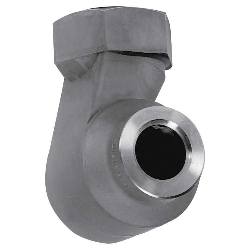
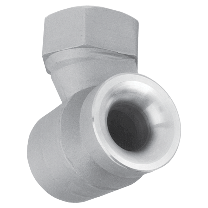
Large free passage
Most uniform liquid distribution around the periphery of the spray
Clog-resistant
No internal parts
One-piece casting
Inlet and outlet are in-line
Silicon carbide requests require review before quote/order acceptance - restrictions may apply
HOW SPRAY PATTERN IS ACHIEVED
Tangential hollow cone nozzles utilize a supply of liquid perpendicular to the direction of spray. Flow enters a swirl chamber without using internal components - allowing for maximum clog resistance.
Available Spray Angles
54 - 95°
Flow Rate Range
4.1 to 892 gpm
Available Connection Types
- Pipe: 1, 1 1/4, 1 1/2, 2, 2 1/2, 3
- Connection Methods: Thread (NPT, BSP, Female)
Materials
Brass, Carbon Steel, 316
Flow Rates, Spray Angles, Connections
Hollow Cone
Select a nozzle number below for performance graph, drawings, and to request a quote.
Flow rate (gpm/lpm) is calculated at differential pressure (psi/bar).
Nozzle Number
Connection Sizes
Spray Angles
Flow Rate (gpm) @ Differential Pressure (psi) (Density: 1 SG)
3 psi
5 psi
10 psi
15 psi
20 psi
40 psi
4.10
5.30
7.49
9.18
10.6
15.0
4.94
6.37
9.01
11.0
12.7
18.0
6.30
8.14
11.5
14.1
16.3
23.0
7.40
9.55
13.5
16.5
19.1
27.0
8.76
11.3
16.0
19.6
22.6
32.0
10.4
13.4
19.0
23.3
26.9
38.0
11.2
14.5
20.5
25.1
29.0
41.0
14.2
18.4
26.0
31.8
36.8
52.0
16.7
21.6
30.5
37.4
43.2
61.0
19.2
24.8
35.1
43.0
49.6
70.2
21.1
27.3
38.6
47.3
54.6
77.2
23.2
30.0
42.4
51.9
59.9
84.7
24.6
31.8
44.9
55.0
63.5
89.8
28.8
37.1
52.5
64.3
74.2
105
34.3
44.3
62.6
76.7
88.5
125
34.8
44.9
63.6
77.8
89.9
127
39.7
51.2
72.4
88.7
102
145
46.6
60.2
85.1
104
120
170
50.7
65.5
92.7
113
131
185
52.0
67.1
94.9
116
134
190
52.7
68.0
96.1
118
136
192
56.1
72.4
102
125
145
205
63.0
81.4
115
141
163
230
76.7
99.1
140
172
198
280
87.6
113
160
196
226
320
93.2
120
170
208
241
340
113
146
206
252
291
412
119
154
218
266
308
435
129
166
235
287
332
469
144
186
263
322
372
526
154
199
282
345
399
564


